NDK Bootloader 开发指南
1. 背景介绍
BootLoader 是一个系统引导程序,用于引导 App 软件初始化、支持 DFU/OTA 升级等。由于实际产品中 BootLoader 是不可以或者很难更新的,因此一个稳定且易用的 BootLoader 是对整个系统的一个基本保障。
NDK 通用 bootloader 例程代码位于:
<PAN10XX-NDK>\01_SDK\nimble\samples\bootloader\目录下NDK 中还有一些方案 App 有自己的 Bootloader 工程,其具体存放位置请参考相关方案文档介绍
2. Bootloader Config 配置
与 App 工程类似,Bootloader 工程中也提供了一个名为 sdk_config.h 的配置文件,但其配置项与 App 中的有所差异:

Bootloader Config File
2.1 Bootloader Config
Bootloader Config 是与当前 Bootloader 工程相关的配置,包括 Bootloader 支持功能的选择、Flash 分区配置等项目:
Enable UART DFU:使能 Bootloader UART DFU 功能
此功能基于 Xmodem 协议实现
Enable USB DFU:使能 Bootloader USB DFU 功能
通过子配置 USB DFU Mode 可以选择当前 USB DFU 升级模式,在不同模式下,USB DFU 上位机工具会执行不同的命令交互流程,具体解释如下:
Select USB DFU mode, which would notify DFU Host (Panchip DFU Tool) to decide what to do when new image has been successfully upgrade to SoC flash (CRC ok). Mode 0: -> [Behavior] a. Jump to App (cmd 0x04 DFU End, param 0x00); b. DFU End -> [Note] For this mode, bootloader itself has responsibility to provide a way for entering USB DFU flow (such as key press event). Mode 1: -> [Behavior] a. Erase DFU flag on flash (cmd 0x06 DFU Force Upgrade, param 0x01); b. Stay in bootloader unless reset; c. DFU End -> [Note] App should set DFU flag to indicate bootloader to enter USB DFU proc. Mode 2: -> [Behavior] a. Erase DFU flag on flash (cmd 0x06 DFU Force Upgrade, param 0x01); b. Jump to App (cmd 0x04 DFU End, param 0x00); c. DFU End -> [Note] App should set DFU flag to indicate bootloader to enter USB DFU proc. Mode 3: -> [Behavior] a. Jump to App (cmd 0x04 DFU End, param 0x00); b. Wait for App USB enum OK; c. App Erase DFU flag on flash (cmd 0x06 DFU Force Upgrade, param 0x01); d. DFU End -> [Note] App should support USB HID, and support the DFU cmd 0x06 (DFU Force Upgrade) to set/erase DFU flag.
默认的 Mode0 支持通过 EVB 按键 KEY2 进入 Bootloader USB DFU 流程
Enable Private 2.4G OTA:使能 Bootloader 私有 2.4G OTA 功能
此功能基于 Panchip 私有 2.4G OTA 升级协议实现
Flash Partition Config:配置与 Bootloader 相关的 Flash 分区起始地址和大小(注意此处 Flash 分区配置需与 App 工程中的 sdk config 配置保持一致!)
Chip Flash Size:指定当前芯片的 Flash 大小,需与实际使用的芯片 Flash 大小保持一致
目前 PAN107x 芯片的 Flash 大小均为 512KB(其中尾部 4KB 为保留区域,存放芯片出厂校准信息,因此用户可用的实际空间为 508KB)
目前 PAN101x 芯片的 Flash 大小均为 256KB(其中尾部 4KB 为保留区域,存放芯片出厂校准信息,因此用户可用的实际空间为 252KB)
Bootloader Flash Partition Size:设置 Bootloader Flash 分区大小(KB)
将此项修改为非 0 值,表示为 Bootloader Image 预留的 Flash 空间大小
App Flash Partition Size:设置当前 App Flash 分区大小(KB)
将此项修改为非 0 值,表示为 App Image 预留的 Flash 空间大小
App Backup Flash Partition Size:设置 App Backup Flash 分区大小(KB)
根据当前项目需要,若需使用 App 备份区(如蓝牙 OTA 场景),则将此项修改为非 0 值
KVStore Flash Partition Size:设置 KVStore Flash 分区大小(KB)
根据当前项目需要,若需使用 KVStore 分区,则将此项修改为非 0 值
User Custom Flash Partition Size:设置 User Custom Flash 分区大小(KB)
根据当前项目需要,若需使用 User Custom 分区,则将此项修改为非 0 值
App Has Image Header:表示 App Image 具有 Image Header
当前 SDK 框架下,若使用 Bootloader,则 App 必须同时使能 App Image Header,所以此选项必须勾上(且应与 App Config 中的对应选项保持一致)
2.2 SoC Platform
SoC Platform 是与芯片平台相关的配置,包括时钟、电源、平台相关的特殊 Feature 等项目。
Bootloader 中的此项菜单实际上是 App Config 中对应项菜单的子集,详情参考 NDK Configuration 指南。
2.3 Log & Debug Config
Log & Debug Config 是与芯片 Log 功能和调试相关的配置。
Bootloader 中的此项菜单实际上与 App Config 中对应项菜单相同,详情参考 NDK Configuration 指南。
3 BootLoader 升级流程和策略
BootLoader 启动的时候,会等待很多个信号,然后依次 trigger 信号的操作。
// signals:
bool sig_key1_push_down(void);
bool sig_key2_push_down(void);
bool sig_ota_start_received(void);
bool sig_back_up_is_completed_image(void);
void sig_hardware_recovery(void);
bool sig_usb_dfu_enter_check(void);

// slots:
void on_usb_dfu_enter(void);
void on_prf_ota_enter(void);
void on_uart_dfu_enter(void);
void on_image_load_enter(void);
连接信号和槽
typedef void (slot_handler_t)(void);
typedef void (signal_handler_t)(void);

void connect(uint8_t priority, signal_handler_t signal, slot_handler_t slot);
事件检测流程
    /* If backup image is valid, the on_image_load_enter function will be handled */
    ss_connect(0, sig_back_up_is_completed_image, on_image_load_enter);

#if BOOT_ENABLE_UART_DFU
    /* when detecting key1 down, the on_uart_dfu_enter function will be handled */
    ss_connect(1, sig_key1_push_down, on_uart_dfu_enter);
#endif

#if BOOT_ENABLE_USB_DFU
#if BOOT_USB_DFU_MODE == 0x00 // Use a GPIO Key to trigger entering USB DFU Mode
    /* If key2 is pressed down, the on_usb_dfu_enter function will be handled */
    ss_connect(2, sig_key2_push_down, on_usb_dfu_enter);
#endif // BOOT_USB_DFU_MODE == 0x00
    /* If the DFU flag on flash is detected, the on_usb_dfu_enter function will be handled */
    ss_connect(3, sig_usb_dfu_enter_check, on_usb_dfu_enter);
#endif // BOOT_ENABLE_USB_DFU

#if BOOT_ENABLE_PRF_OTA
    /* If a 2.4G ota start packet is received, the on_prf_ota_enter function will be handled */
    ss_connect(4, sig_ota_start_received, on_prf_ota_enter);
#endif

    /* Start to handle all of events related signal functions */
    ss_events_handle();
3.1 USB DFU 模式
void on_usb_dfu_enter(void);
进入 DFU 流程,插上 USB 后会将其枚举为 Panchip 自定义的 USB-HID 设备,并准备接收 Panchip USB DFU 上位机工具的交互指令。
3.4 Backup DFU 模式
尝试校验 Flash App Backup 分区中的固件, 以决定是否要将其搬移至 Flash App 分区。
4. UART DFU 升级详解
待升级的固件需要签名校验,默认 keil 编译的时候,在工程的同级 Images 目录下会自动生成带有 .signed 后缀的签名固件:
生成可用于 DFU/OTA 的签名 App 固件
4.1 检测并进入 UART DFU 升级模式
在 Bootloader Config 配置中使能 UART DFU 功能
编写 UART DFU 进入的 Signal 函数,并将信号和槽连接,槽属于升级流程 BootLoader 已经支持,用户不需要修改。用户可以修改 signal 函数。默认如下:
#if BOOT_ENABLE_UART_DFU
    /* when detecting key1 down, the on_uart_dfu_enter function will be handled */
    ss_connect(1, sig_key1_push_down, on_uart_dfu_enter);
#endif

/* user can implement a custom signal fucntion */
bool sig_key1_push_down(void)
{
    GPIO_SetMode(P0, BIT6, GPIO_MODE_INPUT);
    GPIO_EnablePullupPath(P0, BIT6);
    SYS_delay_10nop(10000);

    for (uint16_t i = 0; i < 1000; i++) {
        if (P06 == 1) {
            return false;
        }
    }
    return true;
}
下载 BootLoader 和 App 程序,App 程序配置为带 Bootloader 的方式
4.2 操作流程
准备好 Bootloader Image
准备好待升级的 App Image(例如
ble_periph_hr_ota.signed.bin)使用工具SecureCRT进行升级
打开工具SecureCRT连接设备串口,串口波特率 921600
按住 EVB 底板的 KEY1 按键不松开,然后再按一下 EVB 底板或核心板的 Reset 按钮复位芯片,查看工具 SecureCRT 上 log 打印,一直输出 CCCCCCCCCC:
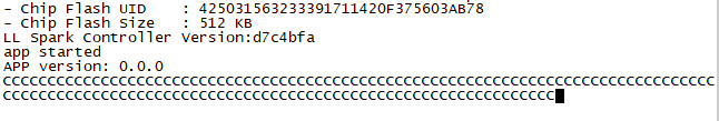
PAN107x UART DFU进入升级模式
在工具 SecureCRT 的”传输”界面选择”发送Xmodem(N)”,选择待升级固件,位于 App 工程
Images路径下:ble_periph_hr_ota.signed.bin,文件开始传输:
PAN107x UART DFU传输文件
再次复位芯片,观察串口 log,确认已经打印升级后的程序 log
5 USB DFU 升级详解
升级的固件需要签名校验,SDK 中 Keil 工程编译的时候,在工程的同级目录 Images 目录下会自动生成带有 .signed 后缀的签名固件:
生成可用于 DFU/OTA 的签名 App 固件
5.1 检测并进入 USB DFU 升级模式
在 Bootloader Config 配置中使能 USB DFU 功能
编写 USB DFU 进入的 signal 函数,并将信号和槽连接,槽属于升级流程 BootLoader 已经支持,用户不需要修改。用户可以修改 signal 函数。默认如下:
#if BOOT_ENABLE_USB_DFU
#if BOOT_USB_DFU_MODE == 0x00 // Use a GPIO Key to trigger entering USB DFU Mode
    /* If key2 is pressed down, the on_usb_dfu_enter function will be handled */
    ss_connect(2, sig_key2_push_down, on_usb_dfu_enter);
#endif // BOOT_USB_DFU_MODE == 0x00
    /* If the DFU flag on flash is detected, the on_usb_dfu_enter function will be handled */
    ss_connect(3, sig_usb_dfu_enter_check, on_usb_dfu_enter);
#endif // BOOT_ENABLE_USB_DFU

/* user can implement a custom signal fucntion */
bool sig_key2_push_down(void)
{
    GPIO_SetMode(P1, BIT2, GPIO_MODE_INPUT);
    GPIO_EnablePullupPath(P1, BIT2);
    SYS_delay_10nop(10000);

    for (uint16_t i = 0; i < 1000; i++) {
        if (P12 == 1) {
             return false;
        }
    }

   return true;
}

bool sig_usb_dfu_enter_check(void)
{
    return is_dfu_flag_valid();
}

/* user can implement a custom dfu flag checking flow */
bool is_dfu_flag_valid(void)
{
	const uint32_t flash_sector_start_addr = CONFIG_FLASH_PARTITION_USER_CUSTOM_ADDR + CONFIG_FLASH_PARTITION_USER_CUSTOM_SIZE - 0x1000; // last user custom sector
	uint8_t dfu_flag;

	dfu_flag = FMC_ReadByte(FLCTL, flash_sector_start_addr, CMD_DREAD);

	if (dfu_flag == USB_DFU_ENTER_FLAG) {
		return true;
	} else {
		return false;
	}
}
下载 BootLoader 和 App 程序,App 程序配置为带 Bootloader 的方式
5.2 操作流程
准备好 Bootloader Image
准备好待升级的 App Image(例如
ble_periph_hr_ota.signed.bin)将 EVB 底板的 USB 口连接到 PC
按住 EVB 底板的 KEY2 按键不松开,然后再按一下 EVB 底板或核心板的 Reset 按钮复位芯片,可从 Log 中观察到成功进入了 Bootloader USB DFU 流程:
Try to load HW calibration data.. DONE.
- Chip Info         : 0x61
- Chip CP Version   : 255
- Chip FT Version   : 7
- Chip MAC Address  : E11000014DE5
- Chip UID          : B90801465454455354
- Chip Flash UID    : 4250315A3538380B01FD8B435603EF78
- Chip Flash Size   : 512 KB (Inc. 4KB Panchip Info Area)

Bootloader in..

[I] Check valid image in App Backup Partition..
[I] Entering USB DFU flow..
[I] Found an App Image, version: 0.0.1.0
[I] USB init done, INT_USBE: 0x1c
[I] Wait for DFU Comm..
[I] ---USB plug in---
[I] USB isr in: Reset evt
[I] USB isr in: Reset evt
打开 NDK 中
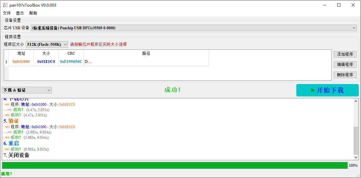
05_TOOLS/量产烧录工具/Panchip DFU Tool目录下的PanchipDFUTool Vx.x.xxx.exe,界面右上角的芯片平台选择 PAN10xx NDK注意:需确保工具版本为
v0.1.015或更高版本
直接点击功能列表中的读取设备版本信息按钮,工具会立刻扫描查找支持 Panchip USB DFU 的 USB-HID 设备,成功后会获取到芯片当前 App 固件版本等信息
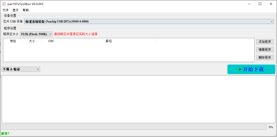
识别 USB 设备并获取芯片当前固件版本信息
在工具程序设置那里选择加载程序,选择待升级工程的文件,位于 Images 路径下:
ble_periph_hr_ota.signed.bin
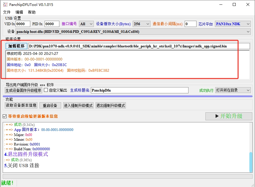
上位机工具成功载入待升级的新固件
程序加载成功后,点击开始升级按钮,稍等片刻即可升级完成
Bootloader USB DFU 升级成功
升级成功后芯片程序会立刻从 Bootloader 跳转到 App 区域执行升级后的新固件
6 PRF OTA 升级详解
打开工具 NDK 中
05_TOOLS/OTA工具/Panchip 2.4G OTA目录下的Panchip 2.4G OTA Vx.x.xxx.exe,选择 2.4G Dongle 对应的串口,具体设置如下图所示:
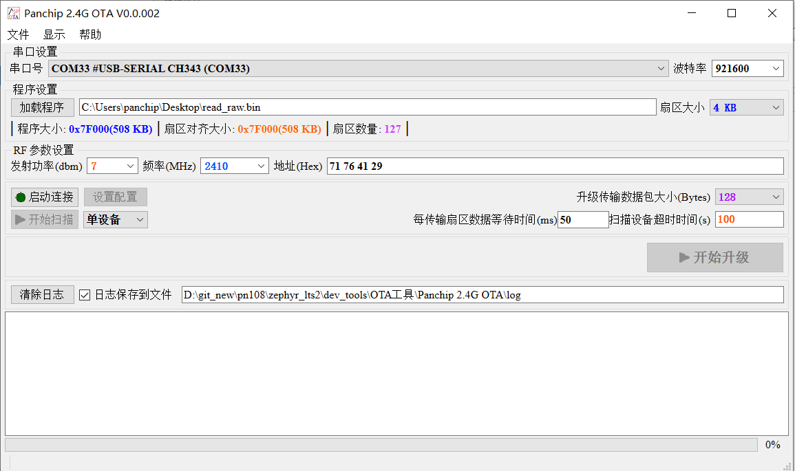
PRF OTA 上位机工具界面
2.4G Dongle 硬件需向 Panchip 申请或购买
上位机工具的使用说明请参考其自带的帮助文档
注意:2.4G 多设备升级不会进行校验,因此不能确保每个设备都能升级成功,有些设备如果升级不成功需要重新升级。
7 在 App 工程中使能 Bootloader
在本文档前面演示 DFU/OTA 升级流程的介绍中,都是以 ble_periph_hr_ota 例程做演示的,原因该例程默认使能了 Bootloader 支持,因此可以直接进行 DFU/OTA 升级演示。
实际上,NDK 中的所有 App 工程均可以通过修改 SDK Config 配置的方式来使能 Bootloader 支持,这里我们以 ble_periph_enc 例程为例:
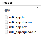
打开 nimble/samples/bluetooth/ble_periph_enc 工程,直接编译,此工程默认未使能 Bootloader 支持,可以看到工程 Images 目录下生成了 3 个文件:
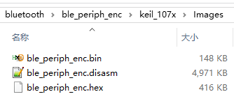
例程 Images 输出目录(未使能 Bootloader)
在 Keil 中打开当前例程的 SDK Config 配置文件(
sdk_config.h),并切换到 Configuration Wizard 界面,修改如下几个配置:
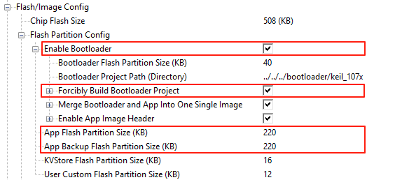
在例程 App SDK Config 中使能 Bootloader 支持
勾选 Flash/Image Config : Flash Partition Config : Enable Bootloader 配置以使能 Bootloader 支持
勾选 Flash/Image Config : Flash Partition Config : Enable Bootloader : Forcibly Build Bootloader Project 配置,在当前 App 工程编译完成后强制编译一次 Bootloader 工程
修改 Flash/Image Config : Flash Partition Config : App Flash Partition Size 配置,由 480 (KB) 改为 220 (KB)
修改 Flash/Image Config : Flash Partition Config : App Backup Flash Partition Size 配置,由 0 (KB) 改为 220 (KB)
使能 Forcibly Build Bootloader Project 配置原因是为了方便演示,实际也可以提前打开并手动编译 Bootloader 工程,这样 App 工程配置中就不需要勾选此选项了
Bootloader Flash Partition 分区默认占用了 40 KB Flash 空间,因此使能 Bootloader 后需重新规划各个 Flash 分区大小,这里我们直接保持其与 Bootloader 工程默认分区配置一致
关于 Flash Partition Config 和 Bootloader Config 配置的详细介绍请参考 NDK Configuration 配置指南 文档中的相关章节
重新编译 App 例程,稍等片刻后即可编译成功(由于前面 SDK Config 配置中使能了 Forcibly Build Bootloader Project 配置,因此在编译 App 工程完成后,还会自动编译一次 Bootloader 工程,所以编译耗时会更久一些),此时可以看到工程 Images 目录下生成了更多文件:
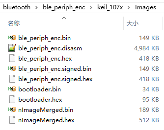
例程 Images 输出目录(使能 Bootloader)
ble_periph_enc.bin:二进制格式的 App Image
ble_periph_enc.disasm:App 反汇编文件
ble_periph_enc.hex:十六进制文本格式的 App Image
ble_periph_enc.signed.bin:签名后的二进制格式的 App Image,可用于 DFU/OTA
ble_periph_enc.signed.hex:签名后的十六进制文本格式的 App Image
bootloader.bin:编译输出的二进制格式 Bootloader Image
bootloader.hex:编译输出的十六进制文本格式 Bootloader Image
nImageMerged.bin:合并了 Bootloader 和 签名后 App Image 的二进制格式 Image
nImageMerged.hex:合并了 Bootloader 和 签名后 App Image 的十六进制文本格式 Image
重要
注意:App 工程在使能 Bootloader 后,若点击 App 工程的 Keil Download 烧录按钮,烧录的仍然是当前 App 固件,而不会烧录 Bootloader 固件或合并后的固件。Bootloader 固件仍需手动打开 Bootloader 工程进行烧录;或者也可使用 PANLink/JFlash 工具直接烧录合并后的固件。
打开 Bootloader 和当前 App 工程,分别点击 Download 按钮,将 Bootloader 和 App 烧录到芯片中,从运行 Log 可以看出系统先执行了 Bootloader 代码,然后跳转到 App 继续运行:
Try to load HW calibration data.. DONE.
- Chip Info         : 0x61
- Chip CP Version   : 3
- Chip FT Version   : 9
- Chip MAC Address  : E1A000095833
- Chip UID          : A56407455338323633
- Chip Flash UID    : 425032323033371410EE02464702B378
- Chip Flash Size   : 512 KB (Inc. 4KB Panchip Info Area)


Bootloader in..

[I] Check valid image in App Backup Partition..
[I] Clean up and try to jump into app image..
[I] - app partition start addr: 0xA000
[I] - app partition size      : 220 KB
[I] - app image header size   : 512 B

Application in..

Try to load HW calibration data.. DONE.
- Chip Info         : 0x61
- Chip CP Version   : 3
- Chip FT Version   : 9
- Chip MAC Address  : E1A000095833
- Chip UID          : A56407455338323633
- Chip Flash UID    : 425032323033371410EE02464702B378
- Chip Flash Size   : 512 KB (Inc. 4KB Panchip Info Area)

- Current Flash Map :
  +-------------------------+ <- Addr: 0x00000
  |  Bootloader Partition   |
  |        ( 40 KB)         |
  +-------------------------+ <- Addr: 0x0A000
  |      App Partition      |
  |        (220 KB)         |
  +-------------------------+ <- Addr: 0x41000
  |  App Backup Partition   |
  |        (220 KB)         |
  +-------------------------+ <- Addr: 0x78000
  |    KVStore Partition    |
  |        ( 16 KB)         |
  +-------------------------+ <- Addr: 0x7C000
  |  User Custom Partition  |
  |        ( 12 KB)         |
  +-------------------------+ <- Addr: 0x7F000
  |    Panchip Info Area    |
  |     (4 KB, Hidden)      |
  +-------------------------+ <- End : 0x80000 (512 KB)

The RCL clock frequency (after calibrate) is 32000 Hz
APP image header check passed, image version: 0.0.1.0

[I] app started
[INF] ble stack init start..
[INF] Spark Controller Init Start
[INF] BLE Heap size:5636 B, remain:64 B
[INF] ble controller version: 0.9.0.03699dd0
[INF] Spark Controller Init OK
[INF] ble host init ok -> ble thread start..

[I] registered service 0x1800 with handle=1
[I]   -registering characteristic 0x2a00 with def_handle=2 val_handle=3
[I]   -registering characteristic 0x2a01 with def_handle=4 val_handle=5
[I] registered service 0x1801 with handle=6
[I]   -registering characteristic 0x2a05 with def_handle=7 val_handle=8
[I]   -registering characteristic 0x2b29 with def_handle=10 val_handle=11
[I]   -registering characteristic 0x2b2a with def_handle=12 val_handle=13
[I] registered service 0x1811 with handle=14
[I]   -registering characteristic 0x2a47 with def_handle=15 val_handle=16
[I]   -registering characteristic 0x2a46 with def_handle=17 val_handle=18
[I]   -registering characteristic 0x2a48 with def_handle=20 val_handle=21
[I]   -registering characteristic 0x2a45 with def_handle=22 val_handle=23
[I]   -registering characteristic 0x2a44 with def_handle=25 val_handle=26
[I] registered service 59462f12-9543-9999-12c8-58b459a2712d with handle=27
[I]   -registering characteristic 33333333-2222-2222-1111-111100000000 with def_handle=28 val_handle=29
[I]     *registering descriptor 34343434-2323-2323-1212-121201010101 with handle=31
[W] Device Id Address: 33:58:09:00:A0:E1
[INF] GAP procedure initiated: advertise;
[INF] disc_mode=2
[INF]  adv_channel_map=0 own_addr_type=0 adv_filter_policy=0 adv_itvl_min=0 adv_itvl_max=0
[I] adv starting
8 产测使用说明
8.1 概述
PAN107x 系列芯片支持在产线生产阶段进入 RF 产测模式,通过 DTM(Direct Test Mode)指令对射频性能进行校准和测试。产测功能通过以下机制实现:
产测固件烧录在 Flash 的 App Backup 分区
Bootloader 检测 App Backup 分区起始位置的产测标志魔法数(
0x12345678),决定是否跳转到产测固件产测完成后,通过 HCI 命令清除产测标志,使设备下次启动时正常进入应用程序
产测固件信息:
产测固件以编译好的二进制形式提供,位于 SDK 路径 05_TOOLS\RF测试固件\PAN107x RF产测固件.zip。解压后包含以下文件:
文件名 |
说明 |
|---|---|
|
产测固件(bin 格式) |
|
产测固件(hex 格式) |
烧录地址:
0x41000(App Backup 分区起始地址)UART 端口:P00(TX)、P01(RX)
波特率:115200
注意:
CFG_RF_MANUFACTOR_TEST功能当前仅 PAN107x 系列芯片支持,PAN101x 系列不支持此功能。
8.2 Flash 分区与地址映射
产测功能涉及以下 Flash 分区(以 PAN107x 512KB Flash、Bootloader 默认分区配置为例):
+-------------------------+ <- Addr: 0x00000
|  Bootloader Partition   |
|        ( 40 KB)         |
+-------------------------+ <- Addr: 0x0A000
|      App Partition      |
|        (220 KB)         |
+-------------------------+ <- Addr: 0x41000  ← CONFIG_FLASH_PARTITION_APP_BACKUP_ADDR
|  App Backup Partition  |     (产测固件烧录于此)
|        (220 KB)         |
+-------------------------+ <- Addr: 0x78000
|    KVStore Partition    |
|        ( 16 KB)         |
+-------------------------+ <- Addr: 0x7C000
|  User Custom Partition  |
|        ( 12 KB)         |
+-------------------------+ <- Addr: 0x7F000
|    Panchip Info Area    |
|     (4 KB, Hidden)      |
+-------------------------+ <- End : 0x80000 (512 KB)
产测固件在 Flash 中的布局:
偏移(相对于 App Backup 起始) |
内容 |
大小 |
|---|---|---|
|
Image Header( |
512 字节 |
|
固件入口向量(MSP 初始值) |
4 字节 |
|
复位向量(入口地址) |
4 字节 |
|
固件代码和数据 |
剩余空间 |
8.3 产测相关命令接口
标准 HCI 命令
命令名 |
Opcode |
说明 |
|---|---|---|
|
|
复位控制器 |
标准 LE DTM 命令
命令名 |
Opcode |
说明 |
|---|---|---|
|
|
LE 接收测试(v1) |
|
|
LE 发射测试(v1) |
|
|
结束 LE 测试,返回接收包数 |
|
|
LE 增强接收测试(v2) |
|
|
LE 增强发射测试(v2) |
厂商自定义 VS 命令
OCF |
命令名 |
Opcode |
说明 |
|---|---|---|---|
|
|
|
设置发射功率 |
|
|
|
单载波发射(定频测试) |
|
|
|
向 Flash 写入标志位(清除产测标志) |
|
|
|
LE 接收测试(VS 扩展) |
|
|
|
LE 发射测试(VS 扩展) |
|
|
|
设置 LE 发射参数 |
|
|
|
进入睡眠模式 |
|
|
|
设置电源模式 |
|
|
|
读取固件版本信息 |
8.4 产测使用步骤
首次部署(产线烧录)
步骤 1:准备固件文件
需要以下三个固件文件:
固件 |
来源 |
说明 |
|---|---|---|
|
Bootloader 工程编译输出 |
Bootloader 固件(位于 Bootloader 工程 |
|
App 工程编译输出 |
应用程序固件(须带 Image Header) |
|
|
产测固件 |
步骤 2:配置 Bootloader 使能产测支持
在 Bootloader 工程 sdk_config.h 中:
#define CFG_RF_MANUFACTOR_TEST 1 // enable RF production test
重新编译 Bootloader 工程,生成更新后的 bootloader.bin。
步骤 3:烧录 Bootloader 和应用程序
方式一:使用 Panchip DFU Tool 烧录合并固件
nImageMerged.bin方式二:使用 JFlash 或 PanLink 分别烧录
bootloader.bin和app.signed.bin
产测执行流程
产测工具:使用 PAN107x ToolBox 或 PRF_BOX 进行产测命令的收发。
步骤 1:设备复位,进入产测模式
复位后,Bootloader 检测到 0x41000 处为 0x12345678,执行 jump_to_rf_test(),跳转到产测固件运行。
步骤 2:连接 HCI UART
使用 PAN107x ToolBox 或 PRF_BOX 连接设备的 HCI UART 接口(P00(TX)/P01(RX)),波特率为 115200。
步骤 3:执行射频测试
通过 HCI 命令或产测工具执行各项射频测试,常用命令及示例如下:
HCI_RESET(复位控制器):
HCI Command: HCI_RESET
Opcode: 0x0C03
Parameter: 无
示例: 01 03 0C 00
LE_Receiver_Test(LE 接收测试 v1):
HCI Command: LE_Receiver_Test
Opcode: 0x201D
Parameter: rxChn (接收信道,0-39 对应 2402-2480 MHz)
示例: 01 1D 20 01 00  (信道0,2402 MHz)
LE_Transmitter_Test(LE 发射测试 v1):
HCI Command: LE_Transmitter_Test
Opcode: 0x201E
Parameter: txChn (发射信道), testDataLen (测试数据长度), pktType (包类型)
示例: 01 1E 20 03 13 25 00  (信道19=2440MHz, 37字节, 伪随机序列)
LE_Test_End(结束 LE 测试):
HCI Command: LE_Test_End
Opcode: 0x201F
Parameter: 无,返回接收包数量
示例: 01 1F 20 00
LE_Enhanced_Receiver_Test(LE 增强接收测试 v2):
HCI Command: LE_Enhanced_Receiver_Test
Opcode: 0x2033
Parameter: rxChn, phy, modulationIndex
示例: 01 33 20 03 13 01 00  (信道19, LE 1M PHY, 标准调制指数)
LE_Enhanced_Transmitter_Test(LE 增强发射测试 v2):
HCI Command: LE_Enhanced_Transmitter_Test
Opcode: 0x2034
Parameter: txChn, testDataLen, pktType, phy
示例: 01 34 20 04 13 25 00 01  (信道19, 37字节, 伪随机, LE 1M PHY)
HCI_OCF_VS_DEBUG_CONSTANT_TONE_V1(单载波发射/定频测试):
HCI Command: HCI_OCF_VS_DEBUG_CONSTANT_TONE_V1
Opcode: 0xFC13
Parameter: freq (频点,0-39 对应 2402-2480 MHz)
示例: 01 13 FC 01 13  (信道19,2440 MHz)
HCI_OCF_VS_DEBUG_LE_TRANSMITTER_TEST(VS 扩展 LE 发射测试):
HCI Command: HCI_OCF_VS_DEBUG_LE_TRANSMITTER_TEST
Opcode: 0xFC18
Parameter: freq, dataLen, payloadType, phy
示例: 01 18 FC 04 13 25 00 01  (信道19, 37字节, 伪随机, LE 1M)
HCI_OCF_VS_DEBUG_LE_RECEIVER_TEST(VS 扩展 LE 接收测试):
HCI Command: HCI_OCF_VS_DEBUG_LE_RECEIVER_TEST
Opcode: 0xFC17
Parameter: freq, phy, modemIndex
示例: 01 17 FC 03 13 01 00  (信道19, LE 1M, 标准调制指数)
HCI_OCF_VS_SET_TX_POWER(设置发射功率):
HCI Command: HCI_OCF_VS_SET_TX_POWER
Opcode: 0xFC10
Parameter: txPower (发射功率值)
示例: 01 10 FC 01 06  (设置发射功率为 6 dBm)
步骤 4:测试完成后清除产测标志
产测完成后,通过 HCI UART 发送 HCI_OCF_VS_SET_FLAG_FLASH 命令清除产测标志:
HCI Command: HCI_OCF_VS_SET_FLAG_FLASH
Opcode: 0xFC16
Parameter: addr (4字节,须4KB对齐), flag (4字节,当前固件忽略此参数)
示例: 01 16 FC 08 00 10 04 00 00 00 00 00  (清除地址 0x41000 处的产测标志)
发送成功后,地址 0x41000 处的 4 字节将被写为 0x00000000。
步骤 5:复位设备,进入正常 App
对设备执行复位(硬件复位或软件复位),Bootloader 检测到 0x41000 处不再为 0x12345678,跳转到正常应用程序执行。
重新进入产测模式
若产测完成后需要再次进入产测模式(如复测),使用 JFlash 等工具,向地址 0x41000 写入 0x12345678,然后复位设备。
8.5 注意事项
Bootloader 侧须使能
CFG_RF_MANUFACTOR_TEST: Bootloader 工程sdk_config.h中的CFG_RF_MANUFACTOR_TEST必须为1,否则 Bootloader 不会检测产测标志。Flash 分区配置一致性: Bootloader 工程与 App 工程中的 Flash 分区配置(
CONFIG_FLASH_PARTITION_*)必须保持一致,否则CONFIG_FLASH_PARTITION_APP_BACKUP_ADDR地址定义不匹配,会导致产测标志检测失败。HCI_OCF_VS_SET_FLAG_FLASH命令的限制: 当前固件实现中,该命令只能清除标志(写入0x00000000),无法设置标志(写入0x12345678)。若需重新进入产测模式,须通过离线烧录工具重新写入魔法数,或在应用程序中实现 Flash 写操作。产测完成后务必清除标志: 若产测标志(
0x41000处的0x12345678)未被清除,设备将始终进入产测模式而无法正常运行 App。产线操作时务必在测试完成后发送HCI_OCF_VS_SET_FLAG_FLASH命令。