DeepSleep GPIO Key Wakeup
1 功能概述
本例程演示如何使 SoC 进入 DeepSleep 状态,然后通过 GPIO 按键将其唤醒。
2 环境准备
硬件设备与线材:
PAN107X EVB 核心板与底板各一块
JLink 仿真器(用于烧录例程程序)
电流计(本文使用电流可视化测量设备 PPK2 [Nordic Power Profiler Kit II] 进行演示)
USB-TypeC 线一条(用于底板供电和查看串口打印 Log)
杜邦线数根或跳线帽数个(用于连接各个硬件设备)
硬件接线:
将 EVB 核心板插到底板上
为确保能够准确地测量 SoC 本身的功耗,排除底板外围电路的影响,请确认 EVB 底板上的:
Voltage 排针组中的 VCC 和 VDD 均接至 3V3
POWER 开关从 LDO 档位拨至 BAT 档位(并确认底板背部的电池座内没有纽扣电池)
使用 USB-TypeC 线,将 PC USB 插口与 EVB 底板 USB->UART 插口相连
使用杜邦线将 EVB 底板上的 TX 引脚接至核心板 P16,RX 引脚接至核心板 P17
使用杜邦线将 JLink 仿真器的:
SWD_CLK 引脚与 EVB 底板的 P00 排针相连
SWD_DAT 引脚与 EVB 底板的 P01 排针相连
SWD_GND 引脚与 EVB 底板的 GND 排针相连
将 PPK2 硬件的:
USB DATA/POWER 接口连接至 PC USB 接口
VOUT 连接至 EVB 底板的 VBAT 排针
GND 连接至 EVB 底板的 GND 排针
PC 软件:
串口调试助手(UartAssist)或终端工具(SecureCRT),波特率 921600(用于接收串口打印 Log)
nRF Connect Desktop(用于配合 PPK2 测量 SoC 电流)
3 编译和烧录
例程位置:<PAN10XX-NDK>\01_SDK\nimble\samples\low_power\deepsleep_gpio_key_wakeup\keil_107x
双击 Keil Project 文件打开工程进行编译烧录,烧录成功后断开 JLink 连线以避免漏电。
4 例程演示说明
PC 上打开 PPK2 Power Profiler 软件,供电电压选择 3300 mV,然后打开供电开关
从串口工具中看到如下的打印信息:
Try to load HW calibration data.. DONE.
- Chip Info         : 0x1
- Chip CP Version   : 255
- Chip FT Version   : 6
- Chip MAC Address  : E11000000FF8
- Chip UID          : 6D0001465454455354
- Chip Flash UID    : 4250315A3538380B005B7B4356037D78
- Chip Flash Size   : 512 KB
APP version: 255.255.65535
Wait for Task Notifications..
此时观察芯片电流波形,发现稳定在 4uA 左右(说明芯片成功进入了 DeepSleep 模式):
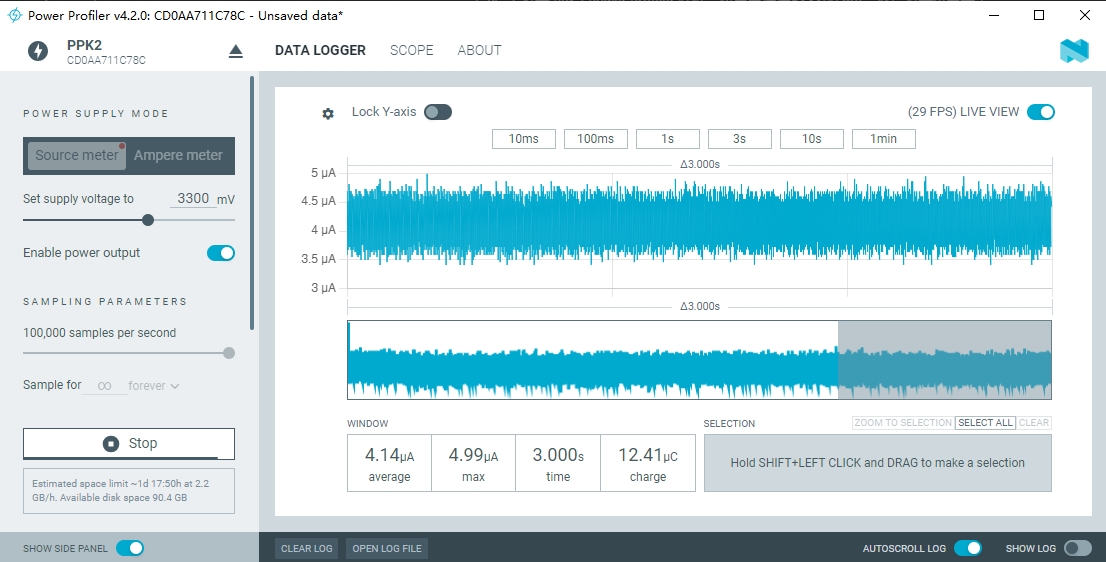
系统初始化后进入 DeepSleep 模式
芯片低功耗状态下的底电流(漏电流)与环境温度相关,温度越高,漏电流越大。
分别尝试按下 EVB 底板上的 3 个按键:KEY1、KEY2 和 WKUP,由串口打印信息可知 3 个按键事件均触发了芯片唤醒:
P0_6 INT occurred.
A notification received, value: 1.

Wait for Task Notifications..
P1_2 INT occurred.
A notification received, value: 1.

Wait for Task Notifications..
P0_2 INT occurred.
A notification received, value: 1.

Wait for Task Notifications..
此时再观察芯片电流波形,可以看到芯片触发了 3 次唤醒,最后又进入 DeepSleep 状态等待下次按键唤醒:
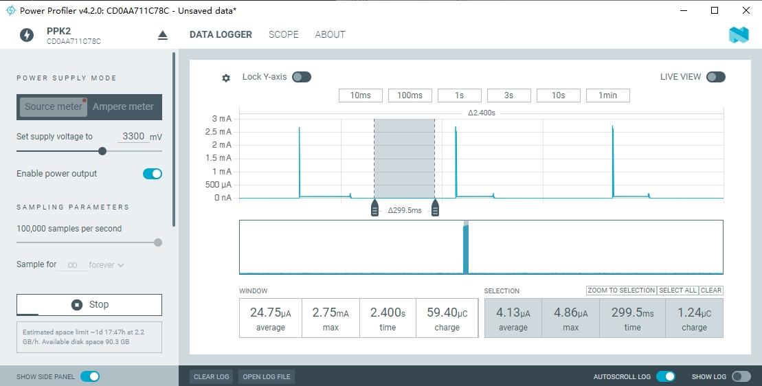
分别使用 3 个按键唤醒芯片
由电流波形可知芯片每次唤醒后均重新进入了 DeepSleep 模式,此模式下芯片电流保持在 4uA 左右。
5 开发者说明
5.1 App Config 配置
本例程的 App Config(对应 app_config_spark.h 文件)配置如下:
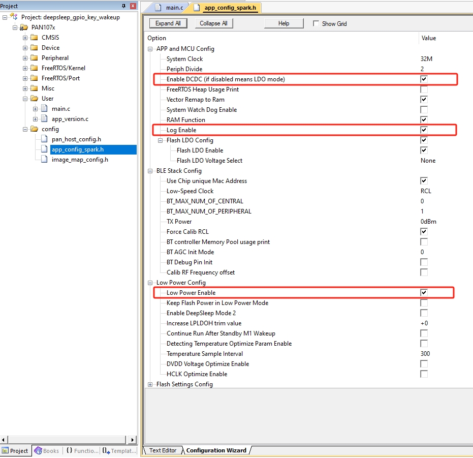
App Config File
其中,与本例程相关的配置有:
Enable DCDC (
CONFIG_SOC_DCDC_PAN1070 = 1):使能芯片 DCDC 供电模式,以降低芯片动态功耗Log Enable (
CONFIG_LOG_ENABLE = 1):使能串口 Log 输出Low Power Enable (
CONFIG_PM = 1):使能系统低功耗流程
5.2 程序代码
5.2.1 主程序
主程序 app_main() 函数内容如下:
void app_main(void)
{
    BaseType_t r;

    print_version_info();

    /* Create an App Task */
    r = xTaskCreate(app_task,                // Task Function
                    "App Task",             // Task Name
                    APP_TASK_STACK_SIZE,    // Task Stack Size
                    NULL,                   // Task Parameter
                    APP_TASK_PRIORITY,      // Task Priority
                    NULL                    // Task Handle
    );

    /* Check if task has been successfully created */
    if (r != pdPASS) {
        printf("Error, App Task created failed!\n");
        while (1);
    }
}
打印 App 版本信息
创建 App 主任务 “App Task”,对应任务函数
app_task确认线程创建成功,否则打印出错信息
5.2.2 App 主任务
App 主任务 app_task() 函数内容如下:
void app_task(void *arg)
{
    uint32_t ulNotificationValue;

    /* Store the handle of current task. */
    xTaskToNotify = xTaskGetCurrentTaskHandle();
    if(xTaskToNotify == NULL) {
        printf("Error, get current task handle failed!\n");
        while (1);
    }

    wakeup_gpio_keys_init();

    while (1) {
        printf("Wait for Task Notifications..\n");

        /*
         * Wait to be notified that gpio key is pressed (gpio irq occured). Note the first parameter
         * is pdTRUE, which has the effect of clearing the task's notification value back to 0, making
         * the notification value act like a binary (rather than a counting) semaphore.
         */
        ulNotificationValue = ulTaskNotifyTake(pdTRUE, portMAX_DELAY);

        printf("A notification received, value: %d.\n\n", ulNotificationValue);
    }
}
获取当前任务的 Task Handle,用于后续中断中给次任务发送通知使用
在 wakeup_gpio_keys_init() 函数中初始化 GPIO 配置
在 while (1) 主循环中尝试获取任务通知(Task Task Notify),并打印相关的状态信息
5.2.3 GPIO 初始化程序
GPIO 初始化程序 wakeup_gpio_keys_init() 函数内容如下:
static void wakeup_gpio_keys_init(void)
{
    /* Configure GPIO P06 (KEY1) / P12 (KEY2) / P02 (WKUP) as Falling Edge Interrupt/Wakeup */

    /* Set pinmux func as GPIO */
    SYS_SET_MFP(P0, 6, GPIO);
    SYS_SET_MFP(P1, 2, GPIO);
    SYS_SET_MFP(P0, 2, GPIO);

    /* Configure debounce clock */
    GPIO_SetDebounceTime(GPIO_DBCTL_DBCLKSRC_RCL, GPIO_DBCTL_DBCLKSEL_4);
    /* Enable input debounce function of specified GPIOs */
    GPIO_EnableDebounce(P0, BIT6);
    GPIO_EnableDebounce(P1, BIT2);
    GPIO_EnableDebounce(P0, BIT2);

    /* Set GPIOs to input mode */
    GPIO_SetMode(P0, BIT6, GPIO_MODE_INPUT);
    GPIO_SetMode(P1, BIT2, GPIO_MODE_INPUT);
    GPIO_SetMode(P0, BIT2, GPIO_MODE_INPUT);
    CLK_Wait3vSyncReady(); /* Necessary for P02 to do manual aon-reg sync */

    /* Enable internal pull-up resistor path */
    GPIO_EnablePullupPath(P0, BIT6);
    GPIO_EnablePullupPath(P1, BIT2);
    GPIO_EnablePullupPath(P0, BIT2);
    CLK_Wait3vSyncReady(); /* Necessary for P02 to do manual aon-reg sync */

    /* Wait for a while to ensure the internal pullup is stable before entering low power mode */
    SYS_delay_10nop(0x10000);

    /* Enable GPIO interrupts and set trigger type to Falling Edge */
    GPIO_EnableInt(P0, 6, GPIO_INT_FALLING);
    GPIO_EnableInt(P1, 2, GPIO_INT_FALLING);
    GPIO_EnableInt(P0, 2, GPIO_INT_FALLING);

    /* Enable GPIO IRQs in NVIC */
    NVIC_EnableIRQ(GPIO0_IRQn);
    NVIC_EnableIRQ(GPIO1_IRQn);
}
此函数使用 Panchip Low-Level GPIO Driver 对 GPIO 进行配置
实际上也可使用更上层的 Panchip HAL GPIO Driver 进行配置,具体可参考GPIO Digital Input Interrupt例程中的相关介绍
由于 EVB 底板上有 3 个按键,分别对应核心板 P06/P12/P02 等 3 个引脚,因此这里仅配置这 3 个 GPIO 引脚:
配置引脚 Pinmux 至 GPIO 功能
使能去抖功能(并配置去抖时间)
使能 GPIO 数字输入模式
使能内部上拉电阻(按键没有外部上拉电阻)
使能 GPIO 中断,将其配置为下降沿触发中断(即下降沿唤醒),并使能相关 NVIC IRQ
5.2.4 GPIO 中断服务程序
GPIO P0 和 P1 的中断服务程序分别如下:
void GPIO0_IRQHandler(void)
{
    BaseType_t xHigherPriorityTaskWoken = pdTRUE;

    for (size_t i = 0; i < 8; i++) {
        if (GPIO_GetIntFlag(P0, BIT(i))) {
            GPIO_ClrIntFlag(P0, BIT(i));
            printf("P0_%d INT occurred.\r\n", i);
            /* Notify the task that gpio key is pressed. */
            vTaskNotifyGiveFromISR(xTaskToNotify, &xHigherPriorityTaskWoken);
        }
    }
}

void GPIO1_IRQHandler(void)
{
    BaseType_t xHigherPriorityTaskWoken = pdTRUE;

    for (size_t i = 0; i < 8; i++) {
        if (GPIO_GetIntFlag(P1, BIT(i))) {
            GPIO_ClrIntFlag(P1, BIT(i));
            printf("P1_%d INT occurred.\r\n", i);
            /* Notify the task that gpio key is pressed. */
            vTaskNotifyGiveFromISR(xTaskToNotify, &xHigherPriorityTaskWoken);
        }
    }
}
每个 GPIO Port 均需编写自己的中断服务函数,其内部可通过
GPIO_GetIntFlag()接口判断触发中断的是当前 port 的哪根 pin在中断服务函数中需注意调用
GPIO_ClrIntFlag()接口清除中断标志位使用 FreeRTOS
vTaskNotifyGiveFromISR()接口向 App Task 发送通知,表示有 GPIO 中断产生(对应按键按下),此接口中xHigherPriorityTaskWoken变量被配置为pdTRUE,表示当中断返回后将会触发线程调度,而对于此例程来说则是重新调度至 App Task 中的ulTaskNotifyTake()处继续执行
5.2.5 与低功耗相关的 Hook 函数
本例程还用到了 2 个与低功耗密切相关的 Hook 函数:
CONFIG_RAM_CODE void vSocDeepSleepEnterHook(void)
{
#if CONFIG_LOG_ENABLE
    reset_uart_io();
#endif
}

CONFIG_RAM_CODE void vSocDeepSleepExitHook(void)
{
#if CONFIG_LOG_ENABLE
    set_uart_io();
#endif
}
FreeRTOS 有一个优先级最低的 Idle Task,当系统调度到此任务后会对当前状态进行检查,以判断是否允许进入芯片 DeepSleep 低功耗流程
若程序执行到 Idle Task 的 DeepSleep 子流程中,会在 SoC 进入 DeepSleep 模式之前执行
vSocDeepSleepEnterHook()函数,在 SoC 从 DeepSleep 模式下唤醒后执行vSocDeepSleepExitHook()函数本例程在
vSocDeepSleepEnterHook()函数中,为防止 UART IO 漏电,编写了相关代码(reset_uart_io(),具体实现见例程源码)以确保在进入 DeepSleep 模式前:串口 Log 数据都打印完毕(即 UART0 Tx FIFO 应为空)
P16 引脚 Pinmux 功能由 UART0 Tx 切换回 GPIO
P17 引脚 Pinmux 功能由 UART0 Rx 切换回 GPIO,并将其数字输入功能关闭
本例程在
vSocDeepSleepExitHook()函数中,编写了相关代码(set_uart_io(),具体实现见例程源码)以恢复串口 Log 打印功能:P16 引脚 Pinmux 功能由 GPIO 重新切换成 UART0 Tx
P17 引脚 Pinmux 功能由 GPIO 重新切换成 UART0 Rx,并将其数字输入功能重新打开