Standby Mode1 SleepTimer Wakeup
1 功能概述
本例程演示如何使 SoC 进入 Standby Mode 1 状态,然后通过 SleepTimer 定时器将其唤醒。
2 环境准备
硬件设备与线材:
PAN107X EVB 核心板与底板各一块
JLink 仿真器(用于烧录例程程序)
电流计(本文使用电流可视化测量设备 PPK2 [Nordic Power Profiler Kit II] 进行演示)
USB-TypeC 线一条(用于底板供电和查看串口打印 Log)
杜邦线数根或跳线帽数个(用于连接各个硬件设备)
硬件接线:
将 EVB 核心板插到底板上
为确保能够准确地测量 SoC 本身的功耗,排除底板外围电路的影响,请确认 EVB 底板上的:
Voltage 排针组中的 VCC 和 VDD 均接至 3V3
POWER 开关从 LDO 档位拨至 BAT 档位(并确认底板背部的电池座内没有纽扣电池)
使用 USB-TypeC 线,将 PC USB 插口与 EVB 底板 USB->UART 插口相连
使用杜邦线将 EVB 底板上的 TX 引脚接至核心板 P16,RX 引脚接至核心板 P17
使用杜邦线将 JLink 仿真器的:
SWD_CLK 引脚与 EVB 底板的 P00 排针相连
SWD_DAT 引脚与 EVB 底板的 P01 排针相连
SWD_GND 引脚与 EVB 底板的 GND 排针相连
将 PPK2 硬件的:
USB DATA/POWER 接口连接至 PC USB 接口
VOUT 连接至 EVB 底板的 VBAT 排针
GND 连接至 EVB 底板的 GND 排针
PC 软件:
串口调试助手(UartAssist)或终端工具(SecureCRT),波特率 921600(用于接收串口打印 Log)
nRF Connect Desktop(用于配合 PPK2 测量 SoC 电流)
3 编译和烧录
例程位置:<PAN10XX-NDK>\01_SDK\nimble\samples\low_power\standby_m1_slptmr_wakeup\keil_107x
双击 Keil Project 文件打开工程进行编译烧录,烧录成功后断开 JLink 连线。
4 例程演示说明
PC 上打开 PPK2 Power Profiler 软件,供电电压选择 3300 mV,然后打开供电开关
从串口工具中看到如下的打印信息:
Try to load HW calibration data.. DONE.
- Chip Info         : 0x1
- Chip CP Version   : 255
- Chip FT Version   : 6
- Chip MAC Address  : E11000000FF8
- Chip UID          : 6D0001465454455354
- Chip Flash UID    : 4250315A3538380B005B7B4356037D78
- Chip Flash Size   : 512 KB
APP version: 255.255.65535

Reset Reason: nRESET Pin Reset.

Busy wait 5s to keep SoC in active mode..
[Uptime: 1083 ms] SleepTimer 1 IRQ triggered.
[Uptime: 2083 ms] SleepTimer 1 IRQ triggered.
[Uptime: 3083 ms] SleepTimer 1 IRQ triggered.
[Uptime: 4083 ms] SleepTimer 1 IRQ triggered.
[Uptime: 5083 ms] SleepTimer 1 IRQ triggered.

Now try to enter SoC standby mode 1 (wakeup reset)..

Try to load HW calibration data.. DONE.
- Chip Info         : 0x1
- Chip CP Version   : 255
- Chip FT Version   : 6
- Chip MAC Address  : E11000000FF8
- Chip UID          : 6D0001465454455354
- Chip Flash UID    : 4250315A3538380B005B7B4356037D78
- Chip Flash Size   : 512 KB
APP version: 255.255.65535

Reset Reason: Standby Mode 1 SleepTimer 1 Wakeup (cnt = 1).

Busy wait 5s to keep SoC in active mode..
[Uptime: 7167 ms] SleepTimer 1 IRQ triggered.
[Uptime: 8167 ms] SleepTimer 1 IRQ triggered.
...
由 Log 中的时间戳可以看出,每隔 1s 触发 SleepTimer 1 中断,触发 5 次中断后,芯片进入 Standby Mode 1,接着被唤醒(复位方式),如此循环
再观察芯片电流波形:
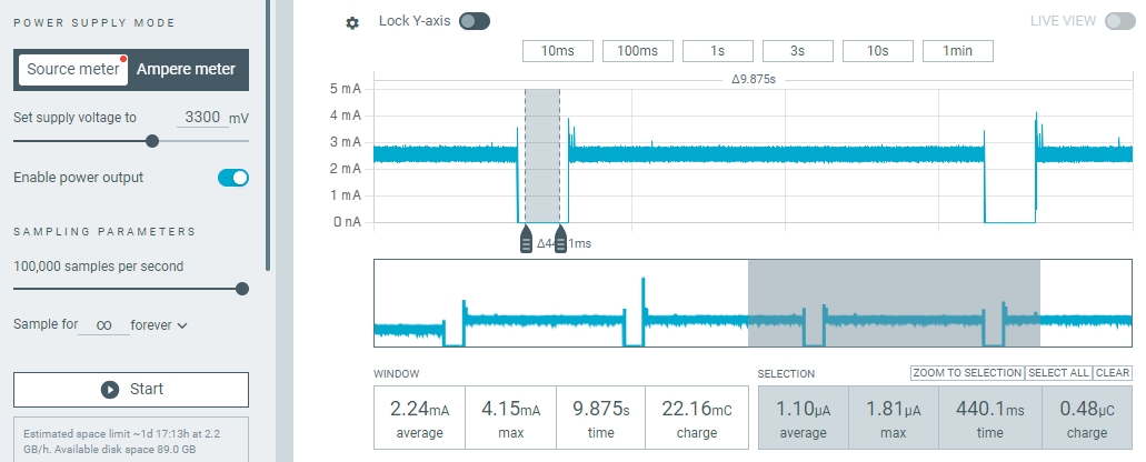
使用电流计抓取电流波形
可见芯片基本上每过 5.5s 左右的时间进入低功耗,底电流为 1.2uA 左右,并在一段时间以后被唤醒,如此循环。
5 开发者说明
5.1 App Config 配置
本例程的 App Config(对应 app_config_spark.h 文件)配置与 Standby Mode1 GPIO Key Wakeup 例程完全相同:
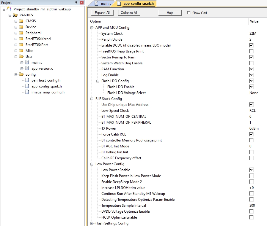
App Config File
5.2 程序代码
5.2.1 主程序
主程序 app_main() 函数内容如下:
void app_main(void)
{
    BaseType_t r;

    print_version_info();

    /* Create an App Task */
    r = xTaskCreate(app_task,               // Task Function
                    "App Task",             // Task Name
                    APP_TASK_STACK_SIZE,    // Task Stack Size
                    NULL,                   // Task Parameter
                    APP_TASK_PRIORITY,      // Task Priority
                    NULL                    // Task Handle
    );

    /* Check if task has been successfully created */
    if (r != pdPASS) {
        printf("Error, App Task created failed!\n");
        while (1);
    }
}
打印 App 版本信息
创建 App 主任务 “App Task”,对应任务函数
app_task确认线程创建成功,否则打印出错信息
5.2.2 App 主任务
App 主任务 app_task() 函数内容如下:
void app_task(void *arg)
{
    uint8_t rst_reason;

    /* Get the last reset reason */
    printf("\nReset Reason: ");
    rst_reason = soc_reset_reason_get();
    switch (rst_reason) {
    case SOC_RST_REASON_POR_RESET:
        printf("Power On Reset.\n");
        break;
    case SOC_RST_REASON_PIN_RESET:
        printf("nRESET Pin Reset.\n");
        break;
    case SOC_RST_REASON_SYS_RESET:
        printf("NVIC System Reset.\n");
        break;
    case SOC_RST_REASON_STBM1_SLPTMR1_WAKEUP:
        printf("Standby Mode 1 SleepTimer 1 Wakeup (cnt = %d).\n", ++wkup_cnt);
        break;
    default:
        printf("Unhandled Reset Reason (%d), refer to more reason define in soc.h!\n", rst_reason);
    }

    /* Init Sleep Timer for wake up use */
    slptmr_init();

    printf("\nBusy wait 5s to keep SoC in active mode..\n");
    soc_busy_wait(5500000);

#if !CONFIG_PM_STANDBY_M1_WAKEUP_WITHOUT_RESET
    printf("\nNow try to enter SoC standby mode 1 (wakeup reset)..\n\n");
#if CONFIG_LOG_ENABLE
    /* Waiting for UART Tx done and re-set UART IO before entering standby mode 1 to avoid current leakage */
    reset_uart_io();
#endif
    /* Enter standby mode1 with all sram power off */
    soc_enter_standby_mode_1(STBM1_WAKEUP_SRC_SLPTMR, STBM1_RETENTION_SRAM_NONE);

    printf("WARNING: Failed to enter SoC standby mode 1 due to unexpected interrupt detected.\n");
    printf("         Please check if there is an unhandled interrupt during the standby mode 1\n");
    printf("         entering flow.\n");

    while (1) {
        /* Busy wait */
    }
#else
    while (1) {
        printf("\nNow try to enter SoC standby mode 1 (wakeup continuous run)..\n\n");
#if CONFIG_LOG_ENABLE
        /* Waiting for UART Tx done and re-set UART IO before entering standby mode 1 to avoid current leakage */
        reset_uart_io();
#endif
        /* Enter standby mode1 with all common 48KB sram retention */
        soc_enter_standby_mode_1(STBM1_WAKEUP_SRC_SLPTMR, STBM1_RETENTION_SRAM_BLOCK0 | STBM1_RETENTION_SRAM_BLOCK1);
        /* Restore hardware peripherals manually */
        restore_hw_peripherals();
        printf("Waked up from SoC standby mode 1 and continue run (cnt = %d)..\n", ++wkup_cnt);
        printf("\nBusy wait 5s to keep SoC in active mode..\n");
        soc_busy_wait(5000000);
    }
#endif /* CONFIG_PM_STANDBY_M1_WAKEUP_WITHOUT_RESET */
}
获取并打印本次芯片启动的复位原因
在 slptmr_init() 函数中初始化 SleepTimer 1 配置
调用
soc_busy_wait()接口使芯片在 Active 状态下全速运行 5.5s根据
CONFIG_PM_STANDBY_M1_WAKEUP_WITHOUT_RESET配置,决定进入 Standby Mode 1 的流程,这里由于我们将此配置设置为 0,因此会执行唤醒后复位的 Standby Mode 1 流程进入 Standby Mode 1 前,先将 Log UART IO 配置还原为 GPIO 模拟输入状态,以避免 Standby 模式下 IO 漏电
调用
soc_enter_standby_mode_1()接口,使系统进入 Standby Mode 1 低功耗状态,此接口接受两个参数:第一个参数用于配置唤醒源,第二个参数用于配置低功耗下保电的 SRAM,这里我们将唤醒源配置为 SleepTimer,且低功耗状态下所有 SRAM 均掉电以节约功耗(由于当前低功耗配置为唤醒后复位,因此所有 SRAM 均没有保电的必要)
5.2.3 SleepTimer 初始化程序
SleepTimer 1 初始化程序 slptmr_init() 函数内容如下:
static void slptmr_init(void)
{
    /* Configure timeout of SleepTimer 1 with interrupt and wakeup enabled */

    /*
     * Configure timeout:
     * timeout1 = SLPTMR1_TIMEOUT_CNT / FREQ_32K_HZ
     *         = (32000 / 1) / 32000 (s)
     *         = 1 s
     */
    const uint32_t SLPTMR1_TIMEOUT_CNT = soc_32k_clock_freq_get() / 1;

    /* Set timeout of SleepTimer 1 */
    LP_SetSleepTime(ANA, SLPTMR1_TIMEOUT_CNT, 1);
}
此函数功能是将 SleepTimer 1 超时时间配置为 1s
配置时间的具体公式计算请参考代码注释
5.2.4 SleepTimer 1 中断服务回调函数
SleepTimer 1 的中断服务回调函数如下:
/* This function overrides the reserved weak function with same name in os_lp.c */
void sleep_timer1_handler(void)
{
    printf("[Uptime: %d ms] SleepTimer 1 IRQ triggered.\n", soc_lptmr_uptime_get_ms());
}
芯片共有 3 个 SleepTimer,分别为 SleepTimer 0、SleepTimer 1 和 SleepTimer 2,它们共用一个中断服务函数
SLPTMR_IRQHandler(),此函数是在 os_lp.c 中实现的;其中 SleepTimer0 被用作 OS Tick,因此在 App 层只可通过回调函数使用 SleepTimer 1 和 SleepTimer 2本例程我们在 App 中实现了
sleep_timer1_handler()中断回调函数,在其中打印芯片上电时间戳 Log
5.2.5 与低功耗相关的 Hook 函数
本例程还用到了 2 个与低功耗密切相关的 Hook 函数:
CONFIG_RAM_CODE void vSocDeepSleepEnterHook(void)
{
#if CONFIG_LOG_ENABLE
    reset_uart_io();
#endif
}

CONFIG_RAM_CODE void vSocDeepSleepExitHook(void)
{
#if CONFIG_LOG_ENABLE
    set_uart_io();
#endif
}
上述两个 Hook 函数用于在进入 DeepSleep 前和从 DeepSleep 唤醒后做一些额外操作,如关闭和重新配置 IO 为串口功能,以防止 DeepSleep 状态下 IO 漏电
详细解释请参考 Standby Mode1 GPIO Key Wakeup 例程中的相关介绍
5.2.6 其他功能函数
本例程还编写了 1 个用于 Standby Mode 1 非 Reset 方式下唤醒后的外设恢复函数:
#if CONFIG_PM_STANDBY_M1_WAKEUP_WITHOUT_RESET
void restore_hw_peripherals(void)
{
#if CONFIG_LOG_ENABLE
    UART_InitTypeDef Init_Struct = {
        .UART_BaudRate = 921600,
        .UART_LineCtrl = Uart_Line_8n1,
    };
    /* Re-init UART */
    UART_Init(UART0, &Init_Struct);
    UART_EnableFifo(UART0);
    /* Set IO pinmux to UART again */
    set_uart_io();
#endif
    /* Re-enable Sleep Timer interrupt */
    NVIC_EnableIRQ(SLPTMR_IRQn);
}
#endif /* CONFIG_PM_STANDBY_M1_WAKEUP_WITHOUT_RESET */
本例程中,我们可以通过手动将
CONFIG_PM_STANDBY_M1_WAKEUP_WITHOUT_RESET配置设置为 1,效果是芯片从 Standby Mode 1 下唤醒后,将不会触发复位,而是从睡眠之前的代码处接着执行,但由于 Standby Mode 1 状态下芯片内部大部分模块均已掉电,因此醒来后需通过函数restore_hw_peripherals()重新初始化一些用到的硬件模块。