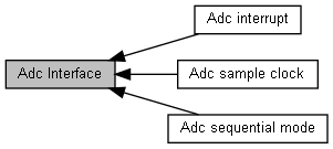
Adc Interface. More...
Modules | |
| Adc interrupt | |
| Adc interrupt control. | |
| Adc sample clock | |
| Adc sample clock time. | |
| Adc sequential mode | |
| Adc sequential mode control. | |
Macros | |
| #define | ADC_INPUTRANGE_HIGH (1UL) |
| #define | ADC_INPUTRANGE_LOW (0UL) |
| #define | ADC_CH8_EXT (0UL) |
| #define | ADC_CH8_BGP (ADC_CHEN_CH8SEL_Msk) |
| #define | ADC_CMP0_LESS_THAN (0UL << ADC_CMP0_CMPCOND_Pos) |
| #define | ADC_CMP1_LESS_THAN (0UL << ADC_CMP1_CMPCOND_Pos) |
| #define | ADC_CMP0_GREATER_OR_EQUAL_TO (1ul << ADC_CMP0_CMPCOND_Pos) |
| #define | ADC_CMP1_GREATER_OR_EQUAL_TO (1ul << ADC_CMP1_CMPCOND_Pos) |
| #define | ADC_TRIGGER_BY_EXT_PIN (0UL << ADC_CTL_HWTRGSEL_Pos) |
| #define | ADC_TRIGGER_BY_PWM (ADC_CTL_HWTRGSEL_Msk) |
| #define | ADC_FALLING_EDGE_TRIGGER (0UL << ADC_CTL_HWTRGCOND_Pos) |
| #define | ADC_RISING_EDGE_TRIGGER (ADC_CTL_HWTRGCOND_Msk) |
| #define | ADC_COMPARATOR_0 (0) |
| #define | ADC_COMPARATOR_1 (1) |
| #define | ADC_FIFO_TRIG_LEVEL_HALF (0) |
| #define | ADC_FIFO_TRIG_LEVEL_FULL (1) |
Functions | |
| __STATIC_INLINE uint32_t | ADC_GetConversionData (ADC_T *ADCx) |
| Get the latest ADC conversion data. More... | |
| __STATIC_INLINE bool | ADC_StatusFlag (ADC_T *ADCx, uint32_t IntMask) |
| Get raw status flag. More... | |
| __STATIC_INLINE void | ADC_ClearStatusFlag (ADC_T *ADCx, uint32_t IntMask) |
| Clear specified interrupt flag. More... | |
| __STATIC_INLINE void | ADC_IntMask (ADC_T *ADCx, uint32_t IntMask, FunctionalState NewState) |
| Set interrupt mask,if masked,interrupt will not be happened. More... | |
| __STATIC_INLINE bool | ADC_IsIntOccured (ADC_T *ADCx, uint32_t IntMask) |
| adjust the user-specified interrupt occured or not More... | |
| __STATIC_INLINE void | ADC_ClearIntFlag (ADC_T *ADCx, uint32_t IntMask) |
| This macro clear the selected interrupt status bits. More... | |
| __STATIC_INLINE bool | ADC_IsBusy (ADC_T *ADCx) |
| Get the busy state of ADC. More... | |
| __STATIC_INLINE bool | ADC_IsDataOverrun (ADC_T *ADCx) |
| Check if the ADC conversion data is over written or not. More... | |
| __STATIC_INLINE bool | ADC_IsDataValid (ADC_T *ADCx) |
| Check if the ADC conversion data is valid or not. More... | |
| __STATIC_INLINE void | ADC_PowerDown (ADC_T *ADCx) |
| Power down ADC module. More... | |
| __STATIC_INLINE void | ADC_PowerOn (ADC_T *ADCx) |
| Power on ADC module. More... | |
| __STATIC_INLINE void | ADC_SequentialModeDisable (ADC_T *ADCx) |
| ADC sequential mode Disabled. More... | |
| __STATIC_INLINE void | ADC_Trigger2Select (ADC_T *ADCx, FunctionalState NewState) |
| TRG1CTL select for 1-shunt sequential mode. More... | |
| __STATIC_INLINE void | ADC_DisableCompare0 (ADC_T *ADCx) |
| Disable comparator 0. More... | |
| __STATIC_INLINE void | ADC_DisableCompare1 (ADC_T *ADCx) |
| Disable comparator 1. More... | |
| __STATIC_INLINE void | ADC_StartConvert (ADC_T *ADCx) |
| Start the A/D conversion. More... | |
| __STATIC_INLINE void | ADC_StopConvert (ADC_T *ADCx) |
| Stop the A/D conversion. More... | |
| __STATIC_INLINE void | ADC_TestModeEnable (ADC_T *ADCx) |
| Enable the A/D test mode. More... | |
| __STATIC_INLINE void | ADC_TestModeDisable (ADC_T *ADCx) |
| Disable the A/D test mode. More... | |
| __STATIC_INLINE void | ADC_DmaModeEnable (ADC_T *ADCx, FunctionalState NewState) |
| Enable the A/D dma mode. More... | |
| __STATIC_INLINE void | ADC_SetClockDivider (ADC_T *ADCx, uint32_t Divider) |
| Set the A/D clock division. More... | |
| __STATIC_INLINE void | ADC_Open (ADC_T *ADCx, uint32_t ChMask) |
| This API configures ADC module to be ready for convert the input from selected channel. More... | |
| __STATIC_INLINE void | ADC_SelInputRange (ADC_T *ADCx, uint32_t EnableHigh) |
| Select ADC range of input sample signal. More... | |
| __STATIC_INLINE void | ADC_TriggerDelay (ADC_T *ADCx, uint32_t Data) |
| Delay ADC start conversion time after PWM trigger. More... | |
| __STATIC_INLINE void | ADC_SetExtraSampleTime (ADC_T *ADCx, uint32_t SampleTime) |
| Set ADC sample time for designated channel. More... | |
| __STATIC_INLINE bool | ADC_IsOneChConvertEnd (ADC_T *ADCx) |
| adjust pwm sequence convert end or not in adc one channel More... | |
| __STATIC_INLINE void | ADC_ClearByHw (ADC_T *ADCx, FunctionalState NewState) |
| clear pwm sequence end flag More... | |
| __STATIC_INLINE void | ADC_LeftShiftEn (ADC_T *ADCx, FunctionalState NewState) |
| enable left shift function,if enable,adc data {adc_output[11:0],4'b0 } More... | |
| __STATIC_INLINE uint32_t | ADC_GetLeftShiftData (ADC_T *ADCx) |
| get left shift data More... | |
| __STATIC_INLINE void | ADC_SubtractBiasEn (ADC_T *ADCx, FunctionalState NewState) |
| enable subtract bias function More... | |
| __STATIC_INLINE void | ADC_SetBiasData (ADC_T *ADCx, uint32_t BiasData) |
| set bias data More... | |
| __STATIC_INLINE uint32_t | ADC_GetLeftBiasData (ADC_T *ADCx) |
| get adc data after bias & left shift More... | |
| __STATIC_INLINE void | ADC_SetFifoTrigLevel (ADC_T *ADCx, uint8_t Level) |
| set adc fifo trig level More... | |
| __STATIC_INLINE uint32_t | ADC_GetFifoPopData (ADC_T *ADCx) |
| get fifo pop data More... | |
| __STATIC_INLINE void | ADC_SeqModeOneChEn (ADC_T *ADCx, FunctionalState NewState) |
| pwm sequential enable in adc one channel mode More... | |
| __STATIC_INLINE void | ADC_SeqModeChSelect (ADC_T *ADCx, uint8_t Ch) |
| adc channel select in pwm sequential More... | |
| void | ADC_Disable (ADC_T *ADCx) |
| Disable ADC Power. More... | |
| void | ADC_Close (void) |
| Close ADC peripheral. More... | |
| void | ADC_EnableHWTrigger (ADC_T *ADCx, uint32_t Source, uint32_t Param) |
| Configure the hardware trigger condition and enable hardware trigger. More... | |
| void | ADC_DisableHWTrigger (ADC_T *ADCx) |
| Disable hardware trigger ADC function. More... | |
| void | ADC_EnableInt (ADC_T *ADCx, uint32_t Mask) |
| Enable the interrupt(s) selected by u32Mask parameter. More... | |
| void | ADC_DisableInt (ADC_T *ADCx, uint32_t Mask) |
| Disable the interrupt(s) selected by u32Mask parameter. More... | |
| void | ADC_SeqModeEnable (ADC_T *ADCx, uint32_t SeqTYPE, uint32_t ModeSel) |
| ADC PWM Sequential Mode Control. More... | |
| void | ADC_SeqModeTriggerSrc (ADC_T *ADCx, uint32_t SeqModeTriSrc) |
| ADC PWM Sequential Mode PWM Trigger Source and type. More... | |
| void | ADC_CompareEnable (ADC_T *ADCx, uint32_t ChNum, uint32_t CmpCondition, uint32_t CmpData, uint32_t MatchCnt, uint32_t CmpSelect) |
| Configure the comparator 0 and enable it. More... | |
| void | ADC_SeqOneChModeConfig (ADC_T *ADCx, uint32_t Trig, uint8_t Level, uint8_t DmaEn, uint8_t HwClrEN, uint8_t AdcCh) |
| set ADC PWM one channel Sequential Mode configuration. More... | |
Detailed Description
Adc Interface.
Macro Definition Documentation
◆ ADC_CH8_BGP
| #define ADC_CH8_BGP (ADC_CHEN_CH8SEL_Msk) |
Use internal band-gap voltage (VBG) as channel 8 source.
◆ ADC_CH8_EXT
| #define ADC_CH8_EXT (0UL) |
Use external input pin as ADC channel 8 source
◆ ADC_CMP0_GREATER_OR_EQUAL_TO
| #define ADC_CMP0_GREATER_OR_EQUAL_TO (1ul << ADC_CMP0_CMPCOND_Pos) |
ADC compare condition greater or equal to
◆ ADC_CMP0_LESS_THAN
| #define ADC_CMP0_LESS_THAN (0UL << ADC_CMP0_CMPCOND_Pos) |
ADC compare condition less than
◆ ADC_CMP1_GREATER_OR_EQUAL_TO
| #define ADC_CMP1_GREATER_OR_EQUAL_TO (1ul << ADC_CMP1_CMPCOND_Pos) |
ADC compare condition greater or equal to
◆ ADC_CMP1_LESS_THAN
| #define ADC_CMP1_LESS_THAN (0UL << ADC_CMP1_CMPCOND_Pos) |
ADC compare condition less than
◆ ADC_COMPARATOR_0
| #define ADC_COMPARATOR_0 (0) |
ADC comparator 0 selected
◆ ADC_COMPARATOR_1
| #define ADC_COMPARATOR_1 (1) |
ADC comparator 0 selected
◆ ADC_FALLING_EDGE_TRIGGER
| #define ADC_FALLING_EDGE_TRIGGER (0UL << ADC_CTL_HWTRGCOND_Pos) |
External pin falling edge trigger ADC
◆ ADC_FIFO_TRIG_LEVEL_FULL
| #define ADC_FIFO_TRIG_LEVEL_FULL (1) |
ADC full fifo threshold level setted
◆ ADC_FIFO_TRIG_LEVEL_HALF
| #define ADC_FIFO_TRIG_LEVEL_HALF (0) |
ADC half fifo threshold level setted
◆ ADC_INPUTRANGE_HIGH
| #define ADC_INPUTRANGE_HIGH (1UL) |
ADC input range 0V~VDD
◆ ADC_INPUTRANGE_LOW
| #define ADC_INPUTRANGE_LOW (0UL) |
ADC input range 0V~1.2V
◆ ADC_RISING_EDGE_TRIGGER
| #define ADC_RISING_EDGE_TRIGGER (ADC_CTL_HWTRGCOND_Msk) |
External pin rising edge trigger ADC
◆ ADC_TRIGGER_BY_EXT_PIN
| #define ADC_TRIGGER_BY_EXT_PIN (0UL << ADC_CTL_HWTRGSEL_Pos) |
ADC trigger by STADC (P3.2) pin
◆ ADC_TRIGGER_BY_PWM
| #define ADC_TRIGGER_BY_PWM (ADC_CTL_HWTRGSEL_Msk) |
ADC trigger by PWM events
Function Documentation
◆ ADC_ClearByHw()
| __STATIC_INLINE void ADC_ClearByHw | ( | ADC_T * | ADCx, |
| FunctionalState | NewState | ||
| ) |
clear pwm sequence end flag
- Parameters
-
[in] ADCx Base address of ADC module [in] NewState new state of clear mode in pwm sequence one channel mode
- Returns
- None
◆ ADC_ClearIntFlag()
| __STATIC_INLINE void ADC_ClearIntFlag | ( | ADC_T * | ADCx, |
| uint32_t | IntMask | ||
| ) |
This macro clear the selected interrupt status bits.
- Parameters
-
[in] ADCx Base address of ADC module [in] IntMask The combination of following interrupt status bits. Each bit corresponds to a interrupt status.
- Returns
- None
◆ ADC_ClearStatusFlag()
| __STATIC_INLINE void ADC_ClearStatusFlag | ( | ADC_T * | ADCx, |
| uint32_t | IntMask | ||
| ) |
Clear specified interrupt flag.
- Parameters
-
[in] ADCx Base address of ADC module [in] IntMask The combination of following status bits. Each bit corresponds to a status flag. - ADC_STATUS_ADCF_Msk
- ADC_STATUS_ADCMPF0_Msk
- ADC_STATUS_ADCMPF1_Msk
- ADC_STATUS_FLAG_FULL_Msk
- ADC_STATUS_FLAG_EMPTY_Msk
- ADC_STATUS_FLAG_OVER_Msk
- ADC_STATUS_FLAG_HALF_Msk
- ADC_STATUS_ADCF_Msk
- Returns
- None
◆ ADC_Close()
| void ADC_Close | ( | void | ) |
Close ADC peripheral.
- Returns
- None
◆ ADC_CompareEnable()
| void ADC_CompareEnable | ( | ADC_T * | ADCx, |
| uint32_t | ChNum, | ||
| uint32_t | CmpCondition, | ||
| uint32_t | CmpData, | ||
| uint32_t | MatchCnt, | ||
| uint32_t | CmpSelect | ||
| ) |
Configure the comparator 0 and enable it.
- Parameters
-
[in] ADCx Base address of ADC module [in] ChNum Specifies the source channel, valid value are from 0 to 7 [in] CmpCondition Specifies the compare condition [in] CmpData Specifies the compare value. Valid value are between 0 ~ 0x3FF [in] MatchCnt Specifies the match count setting, valid values are between 1~16 [in] CmpSelect comparator select,0 or 1
- Returns
- None
For example, ADC_CompareEnable(ADC, 5, ADC_CMP_GREATER_OR_EQUAL_TO, 0x800, 10,ADC_COMPARATOR_0); Means ADC will assert comparator 0 flag if channel 5 conversion result is greater or equal to 0x800 for 10 times continuously.
◆ ADC_Disable()
| void ADC_Disable | ( | ADC_T * | ADCx | ) |
Disable ADC Power.
- Parameters
-
[in] ADCx Base address of ADC module
- Returns
- None
◆ ADC_DisableCompare0()
| __STATIC_INLINE void ADC_DisableCompare0 | ( | ADC_T * | ADCx | ) |
Disable comparator 0.
- Parameters
-
[in] ADCx Base address of ADC module
- Returns
- None
◆ ADC_DisableCompare1()
| __STATIC_INLINE void ADC_DisableCompare1 | ( | ADC_T * | ADCx | ) |
Disable comparator 1.
- Parameters
-
[in] ADCx Base address of ADC module
- Returns
- None
◆ ADC_DisableHWTrigger()
| void ADC_DisableHWTrigger | ( | ADC_T * | ADCx | ) |
Disable hardware trigger ADC function.
- Parameters
-
[in] ADCx Base address of ADC module
- Returns
- None
◆ ADC_DisableInt()
| void ADC_DisableInt | ( | ADC_T * | ADCx, |
| uint32_t | Mask | ||
| ) |
Disable the interrupt(s) selected by u32Mask parameter.
- Parameters
-
[in] ADCx Base address of ADC module [in] Mask The combination of interrupt status bits listed below. Each bit corresponds to a interrupt status. This parameter decides which interrupts will be disabled.
- Returns
- None
◆ ADC_DmaModeEnable()
| __STATIC_INLINE void ADC_DmaModeEnable | ( | ADC_T * | ADCx, |
| FunctionalState | NewState | ||
| ) |
Enable the A/D dma mode.
- Parameters
-
[in] ADCx Base address of ADC module [in] NewState new state of clear mode in pwm sequence one channel mode
- Returns
- None
◆ ADC_EnableHWTrigger()
| void ADC_EnableHWTrigger | ( | ADC_T * | ADCx, |
| uint32_t | Source, | ||
| uint32_t | Param | ||
| ) |
Configure the hardware trigger condition and enable hardware trigger.
- Parameters
-
[in] ADCx Base address of ADC module [in] Source Decides the hardware trigger source. Valid values are: [in] Param While ADC trigger by PWM, this parameter is used to set the delay between PWM trigger and ADC conversion. Valid values are from 0 ~ 0xFF, and actual delay time is (4 * u32Param * HCLK). While ADC trigger by external pin, this parameter is used to set trigger condition. Valid values are:
- Returns
- None
◆ ADC_EnableInt()
| void ADC_EnableInt | ( | ADC_T * | ADCx, |
| uint32_t | Mask | ||
| ) |
Enable the interrupt(s) selected by u32Mask parameter.
- Parameters
-
[in] ADCx Base address of ADC module [in] Mask The combination of interrupt status bits listed below. Each bit corresponds to a interrupt status. This parameter decides which interrupts will be enabled.
- Returns
- None
◆ ADC_GetConversionData()
| __STATIC_INLINE uint32_t ADC_GetConversionData | ( | ADC_T * | ADCx | ) |
Get the latest ADC conversion data.
- Parameters
-
[in] ADCx Base address of ADC module
- Returns
- Latest ADC conversion data
◆ ADC_GetFifoPopData()
| __STATIC_INLINE uint32_t ADC_GetFifoPopData | ( | ADC_T * | ADCx | ) |
get fifo pop data
- Parameters
-
[in] ADCx Base address of ADC module
- Returns
- data value
◆ ADC_GetLeftBiasData()
| __STATIC_INLINE uint32_t ADC_GetLeftBiasData | ( | ADC_T * | ADCx | ) |
get adc data after bias & left shift
- Parameters
-
[in] ADCx Base address of ADC module
- Returns
- data value
◆ ADC_GetLeftShiftData()
| __STATIC_INLINE uint32_t ADC_GetLeftShiftData | ( | ADC_T * | ADCx | ) |
get left shift data
- Parameters
-
[in] ADCx Base address of ADC module
- Returns
- data value
◆ ADC_IntMask()
| __STATIC_INLINE void ADC_IntMask | ( | ADC_T * | ADCx, |
| uint32_t | IntMask, | ||
| FunctionalState | NewState | ||
| ) |
Set interrupt mask,if masked,interrupt will not be happened.
- Parameters
-
[in] ADCx Base address of ADC module [in] u32Mask The combination of following interrupt mask bits. Each bit corresponds to a interrupt mask flag. - ADC_STATUS_INTMSK_FULL_Msk
- ADC_STATUS_INTMSK_EMPTY_Msk
- ADC_STATUS_INTMSK_OVER_Msk
- ADC_STATUS_INTMSK_HALF_Msk
- ADC_STATUS_INTMSK_AD_Msk
- ADC_STATUS_INTMSK_CMP0_Msk
- ADC_STATUS_INTMSK_CMP1_Msk
[in] NewState new state of adc interrupt mask - ADC_STATUS_INTMSK_FULL_Msk
- Returns
- none
◆ ADC_IsBusy()
| __STATIC_INLINE bool ADC_IsBusy | ( | ADC_T * | ADCx | ) |
Get the busy state of ADC.
- Parameters
-
[in] ADCx Base address of ADC module
- Returns
- busy state of ADC
- Return values
-
0 ADC is not busy 1 ADC is busy
◆ ADC_IsDataOverrun()
| __STATIC_INLINE bool ADC_IsDataOverrun | ( | ADC_T * | ADCx | ) |
Check if the ADC conversion data is over written or not.
- Parameters
-
[in] ADCx Base address of ADC module
- Returns
- Over run state of ADC data
- Return values
-
0 ADC data is not overrun 1 ADC data is overrun
◆ ADC_IsDataValid()
| __STATIC_INLINE bool ADC_IsDataValid | ( | ADC_T * | ADCx | ) |
Check if the ADC conversion data is valid or not.
- Parameters
-
[in] ADCx Base address of ADC module
- Returns
- Valid state of ADC data
- Return values
-
0 ADC data is not valid 1 ADC data us valid
◆ ADC_IsIntOccured()
| __STATIC_INLINE bool ADC_IsIntOccured | ( | ADC_T * | ADCx, |
| uint32_t | IntMask | ||
| ) |
adjust the user-specified interrupt occured or not
- Parameters
-
[in] ADCx Base address of ADC module [in] IntMask The combination of following interrupt status bits. Each bit corresponds to a interrupt status.
- Returns
- User specified interrupt flags
◆ ADC_IsOneChConvertEnd()
| __STATIC_INLINE bool ADC_IsOneChConvertEnd | ( | ADC_T * | ADCx | ) |
adjust pwm sequence convert end or not in adc one channel
- Parameters
-
[in] ADCx Base address of ADC module
- Returns
- true of false
◆ ADC_LeftShiftEn()
| __STATIC_INLINE void ADC_LeftShiftEn | ( | ADC_T * | ADCx, |
| FunctionalState | NewState | ||
| ) |
enable left shift function,if enable,adc data {adc_output[11:0],4'b0 }
- Parameters
-
[in] ADCx Base address of ADC module [in] NewState new state of left shift function
- Returns
- None
◆ ADC_Open()
| __STATIC_INLINE void ADC_Open | ( | ADC_T * | ADCx, |
| uint32_t | ChMask | ||
| ) |
This API configures ADC module to be ready for convert the input from selected channel.
- Parameters
-
[in] ADCx Base address of ADC module [in] ChMask Channel enable bit. Each bit corresponds to a input channel. Bit 0 is channel 0, bit 1 is channel 1...
- Returns
- None
- Note
- Panchip series MCU ADC can only convert 1 channel at a time. If more than 1 channels are enabled, only channel with smallest number will be convert.
- This API does not turn on ADC power nor does trigger ADC conversion
◆ ADC_PowerDown()
| __STATIC_INLINE void ADC_PowerDown | ( | ADC_T * | ADCx | ) |
Power down ADC module.
- Parameters
-
[in] ADCx Base address of ADC module
- Returns
- None
◆ ADC_PowerOn()
| __STATIC_INLINE void ADC_PowerOn | ( | ADC_T * | ADCx | ) |
Power on ADC module.
- Parameters
-
[in] ADCx Base address of ADC module
- Returns
- None
◆ ADC_SelInputRange()
| __STATIC_INLINE void ADC_SelInputRange | ( | ADC_T * | ADCx, |
| uint32_t | EnableHigh | ||
| ) |
Select ADC range of input sample signal.
- Parameters
-
[in] ADCx Base address of ADC module [in] EnableHigh If EnableHigh is 1,adc input range is 0V~VDD;if u32EnableHigh is 0,adc input range is 0V~1.2V. 0V~VDD & 0V~1.2V both is theoretical value,the real range is determined by bandgap voltage.
- Returns
- None
◆ ADC_SeqModeChSelect()
| __STATIC_INLINE void ADC_SeqModeChSelect | ( | ADC_T * | ADCx, |
| uint8_t | Ch | ||
| ) |
adc channel select in pwm sequential
- Parameters
-
[in] ADCx Base address of ADC module [in] Ch adc channel select
- Returns
- None
◆ ADC_SeqModeEnable()
| void ADC_SeqModeEnable | ( | ADC_T * | ADCx, |
| uint32_t | SeqTYPE, | ||
| uint32_t | ModeSel | ||
| ) |
ADC PWM Sequential Mode Control.
- Parameters
-
[in] ADCx Base address of ADC module [in] SeqTYPE This parameter decides which type will be selected. [in] ModeSel This parameter decides which mode will be selected.
- Returns
- None
◆ ADC_SeqModeOneChEn()
| __STATIC_INLINE void ADC_SeqModeOneChEn | ( | ADC_T * | ADCx, |
| FunctionalState | NewState | ||
| ) |
pwm sequential enable in adc one channel mode
- Parameters
-
[in] ADCx Base address of ADC module [in] NewState new state of adc sequence mode
- Returns
- None
◆ ADC_SeqModeTriggerSrc()
| void ADC_SeqModeTriggerSrc | ( | ADC_T * | ADCx, |
| uint32_t | SeqModeTriSrc | ||
| ) |
ADC PWM Sequential Mode PWM Trigger Source and type.
- Parameters
-
[in] ADCx Base address of ADC module [in] SeqModeTriSrc This parameter decides first PWM trigger source and type.
- Returns
- None
◆ ADC_SeqOneChModeConfig()
| void ADC_SeqOneChModeConfig | ( | ADC_T * | ADCx, |
| uint32_t | Trig, | ||
| uint8_t | Level, | ||
| uint8_t | DmaEn, | ||
| uint8_t | HwClrEN, | ||
| uint8_t | AdcCh | ||
| ) |
set ADC PWM one channel Sequential Mode configuration.
- Parameters
-
[in] ADCx Base address of ADC module [in] Trig This parameter decides first PWM trigger source and type. [in] Level This parameter decides fifo threshold value. [in] DmaEn This parameter decides dma is used or not. [in] HwClrEN This parameter decides PWM trigger flag cleared by hardware or software. [in] AdcCh This parameter decides which adc channel selected.
- Returns
- None
◆ ADC_SequentialModeDisable()
| __STATIC_INLINE void ADC_SequentialModeDisable | ( | ADC_T * | ADCx | ) |
ADC sequential mode Disabled.
- Parameters
-
[in] ADCx Base address of ADC module
- Returns
- None
◆ ADC_SetBiasData()
| __STATIC_INLINE void ADC_SetBiasData | ( | ADC_T * | ADCx, |
| uint32_t | BiasData | ||
| ) |
set bias data
- Parameters
-
[in] ADCx Base address of ADC module [in] BiasData data value
- Returns
- none
◆ ADC_SetClockDivider()
| __STATIC_INLINE void ADC_SetClockDivider | ( | ADC_T * | ADCx, |
| uint32_t | Divider | ||
| ) |
Set the A/D clock division.
- Parameters
-
[in] ADCx Base address of ADC module [in] Divider Adc clk divider
- Returns
- None
◆ ADC_SetExtraSampleTime()
| __STATIC_INLINE void ADC_SetExtraSampleTime | ( | ADC_T * | ADCx, |
| uint32_t | SampleTime | ||
| ) |
Set ADC sample time for designated channel.
- Parameters
-
[in] ADCx Base address of ADC module [in] SampleTime ADC sample ADC time, valid values are
- Returns
- None
◆ ADC_SetFifoTrigLevel()
| __STATIC_INLINE void ADC_SetFifoTrigLevel | ( | ADC_T * | ADCx, |
| uint8_t | Level | ||
| ) |
set adc fifo trig level
- Parameters
-
[in] ADCx Base address of ADC module [in] Level dma request level ADC_FIFO_TRIG_LEVEL_HALF ADC_FIFO_TRIG_LEVEL_FULL
- Returns
- none
◆ ADC_StartConvert()
| __STATIC_INLINE void ADC_StartConvert | ( | ADC_T * | ADCx | ) |
Start the A/D conversion.
- Parameters
-
[in] ADCx Base address of ADC module
- Returns
- None
◆ ADC_StatusFlag()
| __STATIC_INLINE bool ADC_StatusFlag | ( | ADC_T * | ADCx, |
| uint32_t | IntMask | ||
| ) |
Get raw status flag.
- Parameters
-
[in] ADCx Base address of ADC module [in] IntMask The combination of following status bits. Each bit corresponds to a status flag. - ADC_STATUS_ADCF_Msk
- ADC_STATUS_ADCMPF0_Msk
- ADC_STATUS_ADCMPF1_Msk
- ADC_STATUS_FLAG_FULL_Msk
- ADC_STATUS_FLAG_EMPTY_Msk
- ADC_STATUS_FLAG_OVER_Msk
- ADC_STATUS_FLAG_HALF_Msk
- ADC_STATUS_ADCF_Msk
- Returns
- True or false
◆ ADC_StopConvert()
| __STATIC_INLINE void ADC_StopConvert | ( | ADC_T * | ADCx | ) |
Stop the A/D conversion.
- Parameters
-
[in] ADCx Base address of ADC module
- Returns
- None
◆ ADC_SubtractBiasEn()
| __STATIC_INLINE void ADC_SubtractBiasEn | ( | ADC_T * | ADCx, |
| FunctionalState | NewState | ||
| ) |
enable subtract bias function
- Parameters
-
[in] ADCx Base address of ADC module [in] NewState new state of subtract bias function
- Returns
- None
◆ ADC_TestModeDisable()
| __STATIC_INLINE void ADC_TestModeDisable | ( | ADC_T * | ADCx | ) |
Disable the A/D test mode.
- Parameters
-
[in] ADCx Base address of ADC module
- Returns
- None
◆ ADC_TestModeEnable()
| __STATIC_INLINE void ADC_TestModeEnable | ( | ADC_T * | ADCx | ) |
Enable the A/D test mode.
- Parameters
-
[in] ADCx Base address of ADC module
- Returns
- None
◆ ADC_Trigger2Select()
| __STATIC_INLINE void ADC_Trigger2Select | ( | ADC_T * | ADCx, |
| FunctionalState | NewState | ||
| ) |
TRG1CTL select for 1-shunt sequential mode.
- Parameters
-
[in] ADCx Base address of ADC module [in] NewState new state of adc sequence mode
- Returns
- None
◆ ADC_TriggerDelay()
| __STATIC_INLINE void ADC_TriggerDelay | ( | ADC_T * | ADCx, |
| uint32_t | Data | ||
| ) |
Delay ADC start conversion time after PWM trigger.
- Parameters
-
[in] ADCx Base address of ADC module [in] Data for Delay time
- Returns
- None